Wire Sizing Calculator
Code-aware calculator with cost analysis, educational tooltips, and real-world examples for DIY solar installers in Canada.
📊 Quick Reference - Common Solar Wire Sizes
⚡ Interactive Wiring Diagram — Click Any Wire or Component
Not sure which part of your system you're sizing? Click any wire or component in the diagram below — we'll explain what it does, pre-fill the calculator with typical values, and show you the right product to buy.
👆 Tap any highlighted zone to explore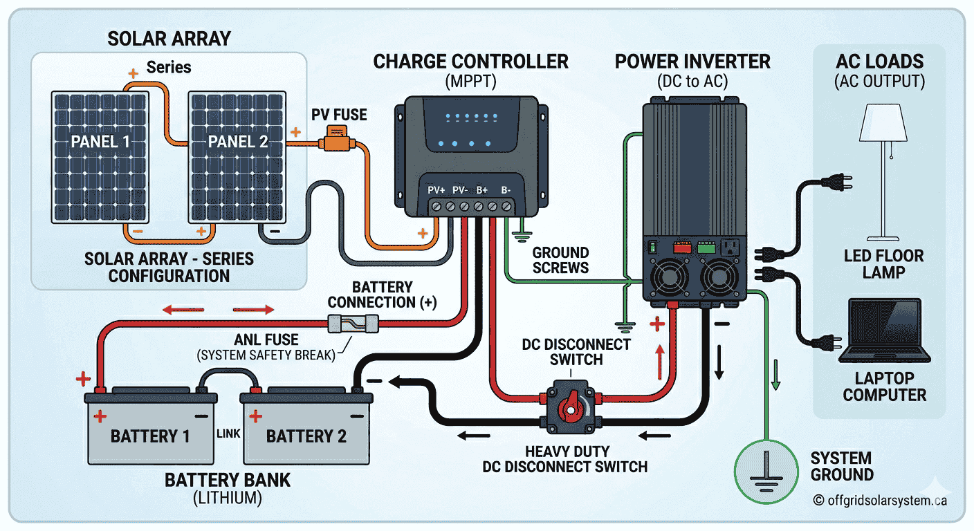
© offgridsolarsystem.ca — Interactive diagram. All rights reserved.
💡 Common Off-Grid Application Examples
💡 Pro Tips for Wire Selection
📊 Wire Gauge Quick Reference
| AWG | Max Amps Cu (75°C) |
Max Amps Al (75°C) |
Diameter (mm) |
Common Use |
|---|---|---|---|---|
| 14 | 20A | 15A | 1.6mm | Lighting circuits |
| 12 | 25A | 20A | 2.0mm | General outlets |
| 10 | 35A | 30A | 2.6mm | Small charge controllers Shop 10 AWG → |
| 8 | 50A | 40A | 3.3mm | Medium solar arrays Shop 8 AWG → |
| 6 | 65A | 50A | 4.1mm | Large charge controllers Shop 6 AWG → |
| 4 | 85A | 65A | 5.2mm | Battery banks (short runs) Shop 4 AWG → |
| 2 | 115A | 95A | 6.5mm | Inverter DC input Shop 2 AWG → |
| 2/0 | 175A | 145A | 9.3mm | Large battery banks Shop 2/0 → |
☀️ Solar Panel Wire (PV/USE-2 Rated)
For panel-to-charge-controller and panel-to-combiner-box runs. Must be UV-resistant, rated for wet locations, and sunlight-resistant. USE-2 or PV-rated wire is required by CEC Section 64 for outdoor solar applications.
10 AWG Solar Wire (30A max · Charge controller circuits)
Best for: Panel strings to MPPT/PWM charge controllers up to 30A. Look for tinned copper, dual-insulated, 10 AWG USE-2/PV wire.
Shop 10 AWG Solar Wire on Amazon →8 AWG Solar Wire (40A max · Medium arrays · Longer runs)
Best for: Arrays over 400W or runs over 5 metres where voltage drop requires a step up from 10 AWG.
Shop 8 AWG Solar Wire on Amazon →6 AWG Solar Wire (55A max · Large arrays · Long runs)
Best for: High-current panel strings (over 40A), long cable runs over 10 metres, or 48V systems with large arrays.
Shop 6 AWG Solar Wire on Amazon →🔋 Battery Bank Cables (Welding Cable)
Battery connections carry your system's highest currents. Welding cable is the preferred choice: it's highly flexible in cold Canadian weather and handles high current surges efficiently.
4 AWG Welding Cable (70A max · Small battery banks)
Best for: Small 12V or 24V systems up to 800W inverters. Ideal for battery-to-busbar connections.
Shop 4 AWG Welding Cable →2 AWG Welding Cable (95A max · Most common battery gauge)
Best for: 24V systems up to 2000W inverters and 48V systems up to 4000W. The classic off-grid cabin standard.
Shop 2 AWG Welding Cable →2/0 AWG Welding Cable (130A+ max · Large inverters)
Best for: 48V systems with 3000W+ heavy duty inverters and massive LiFePO4 battery banks.
Shop 2/0 AWG Welding Cable →🔌 Connectors & Accessories
Every solar installation needs these. Buy them alongside your main wire spools to keep delivery configurations simple.
MC4 Connector Kit
Required for every single solar panel termination. Always buy IP67 waterproof-rated configurations.
Shop MC4 Connector Kit →Copper Ring Terminal Lugs
For heavy battery terminal hookups. Fits 2 AWG and 4 AWG configurations perfectly with standard M8 terminal ports.
Shop Ring Terminal Lugs →MC4 Inline Fuse Holder (30A)
Critical string protection needed to comply with safety layouts between your arrays and charge controllers.
Shop MC4 Inline Fuse Holder →Adhesive-Lined Heat Shrink Tubing
Dual-wall assortments to trap out moisture completely. Crucial step for cold weather exposures across Canada.
Shop Heat Shrink Tubing →How Wire Sizing Works
Proper wire sizing in off-grid solar systems is critical for two main reasons: safety and efficiency. When electricity flows through wire, it encounters resistance, which causes voltage drop and heat generation.
Voltage Drop
As electricity travels through wire, some voltage is "lost" due to the wire's resistance. This lost voltage reduces the power available to your equipment and can cause poor performance. In solar systems, excessive voltage drop means you're not getting the full power from your panels or batteries.
Ampacity (Current Capacity)
Every wire size has a maximum safe current capacity called ampacity. Exceeding this limit causes dangerous overheating, which can melt insulation, start fires, or damage equipment. The National Electrical Code (NEC) provides ampacity ratings for different wire types and installation conditions.
Safety Factors
Off-grid solar systems require additional safety considerations. Both the Canadian Electrical Code (CEC) and US National Electrical Code (NEC) mandate that continuous loads (running for 3+ hours) must not exceed 80% of the circuit's rated capacity. This is why we apply the 125% rule - multiply your continuous current by 1.25 when sizing wire and breakers.
Formulas & Calculations
Voltage Drop Calculation (DC)
The basic formula for calculating voltage drop in DC circuits:
Voltage Drop Calculation (AC)
Percentage Voltage Drop
Wire Size (Circular Mils) Calculation
To find the minimum wire size needed:
CEC 125% Continuous Load Rule
Related Solar & Energy Calculators
Frequently Asked Questions
References & Standards
Canadian Electrical Code (CEC)
- CEC Section 64: Solar Photovoltaic Systems - Canadian requirements for solar installations including wire sizing, grounding, and safety disconnects.
- CEC Section 14: Protection and Control - Defines overcurrent protection requirements and the 125% continuous load rule.
- CEC Section 4: Conductors - Contains ampacity tables and derating factors for Canadian installation conditions.
- CEC Table 2: Allowable ampacities for copper conductors - Primary reference for wire current capacity in Canada.
US National Electrical Code (NEC) - For Reference
- NEC Article 690: Solar Photovoltaic (PV) Systems - Similar principles to CEC Section 64, widely referenced internationally.
- NEC Article 240: Overcurrent Protection - Harmonized with CEC protection requirements.
- NEC Article 310: Conductors for General Wiring - Ampacity tables similar to CEC Section 4.
Canadian Standards & Certifications
- CSA C22.2 No. 230: Solar Modules - Canadian safety standard for photovoltaic modules and systems.
- CSA C61215: Crystalline Silicon Terrestrial Photovoltaic Modules - Design qualification and type approval.
- CSA C22.2 No. 0.3: Test Methods for Electrical Wires and Cables - Standards for Canadian wire testing.
- Canadian Standards Association (CSA): Primary certification body for electrical equipment used in Canada.